DRC Help - Filter
If you consider the oscillators the soul of a synth, the filter is definitely the body. It restricts the soul but at the same time it adds a whole different dimension unattainable by any other mean. A lot of attention and time was dedicated to the design of the DRC filters and a lot of the overall character comes from this piece of code. We analyzed lots of classic analog Ladder Filter Topologies, analog Multimode Filter implementations and tried to capture every little nuance of the most interesting examples.
In the FILTER PANEL you have access to every parameter regarding the Filter module and the VCA (Voltage Controlled Amplifier) module.
Pressing FILTER will bring you back to the default tab which is the MAIN TAB. In DRC the audio path is as follows OSCILLATORS > MIXER > FILTER > VCA > FX
Main Controls

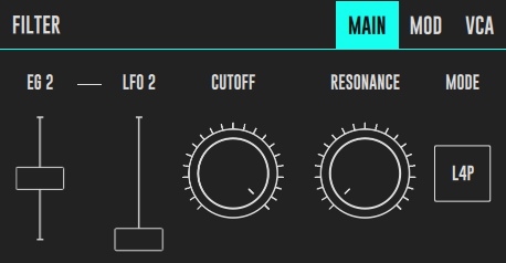
This tab is where you can access the main filter controls. The focus here is to be able to control the filter parameters in real time, with big knobs and an overall uncluttered interface. This is key to enhance expression and sound sculpting in real time. The MAIN TAB also the default tab for the FILTER PANEL, so you can press MAIN or FILTER to get here quickly.
Parameters
-
CUTOFF - This knob controls the cutoff frequency of the filter. The cutoff frequency is the frequency where the filter begins doing its job cutting frequencies. The basis of Subtractive Synthesis is that you generate an harmonically rich waveform in the Oscillators and then filter out frequency content in the Filter.
-
RESONANCE - The resonance occurs when the output from the filter is fed back to the input internally (with some caveats), creating a peak at the cutoff frequency. The RESONANCE knob controls the amount of resonance you create this way. IT is used to make the filter more aggressive. In the L4P Filter Type the Resonance is able to create such a peak that it creates self oscillation converting the filter in a sine wave oscillator. Remember you will only hear it if you press a key because you need to open the VCA in order to hear what comes out of the filter, and if you use KBD (keyboard follow) modulation you can play this filter.
-
EG 2 - This slider controls the amount of the EG 2 (Envelope Generator 2) that affects the filter cutoff. This is the most important modulation to the Filter and thats the reason it is placed in the MAIN TAB, and all the other modulations are in the MOD TAB.
-
LFO 2 - This slider controls the amount of modulation that is applied to the EG 2 parameter allowing more intricate filter results. You change all the characteristics of the LFO2 waveform in the MODIFIERS PANEL > LFO 2 TAB.
-
MODE - The MODE toggle button allows you to switch between all the different Filter Modes DRC offers:
-
L4P - 4 pole Lowpass Filter (24dB/oct attenuation) - A Lowpass Filter type allows low frequency content to pass through cutting high frequency content at a rate defined by the number of poles.This filter type is a digital implementation of the Moog Transistor Ladder Filter.
-
L2P - 2 pole Lowpass Filter (12dB/oct - thus less frequency cutting effect than the L4P) - This filter is a digital implementation of an analog multimode filter topology in the Lowpass Mode. A Lowpass Filter type allows low frequency content to pass through cutting high frequency content at a rate defined by the number of poles.
-
B2P - 2 pole Bandpass Filter (12dB/oct) - The 2pole bandpass filter allows only a restricted frequency band to pass throw cutting frequencies below and above at a 12dB per octave rate. In this filter the Resonance has a particular importance as it somewhat defines the bandwidth that can get through the filter.This filter represents the bandpass output of the analog multiband filter implementation.
-
H2P - 2 pole Highpass Filter (12dB/oct) - A 2 pole Highpass Filter type allows high frequency content to pass through cutting low frequency content at a rate defined by the number of poles. This filter represents the highpass output of the analog multiband filter implementation.
-
NOTCH - A notch filter is a filter that cuts only a very restric band of frequencies, you can think of it as a more aggressive form of bandpass, that instead of allowing a band to pass it cuts that band out. This filter is also a product of the multimode filter topology used in the other filters (except L4P). It gives the sound a sort of hollowness that can be interesting in some situations, if you use an LFO to modulate this filter you will get an effect that resembles a phaser. Try using with low resonance.
Modulation

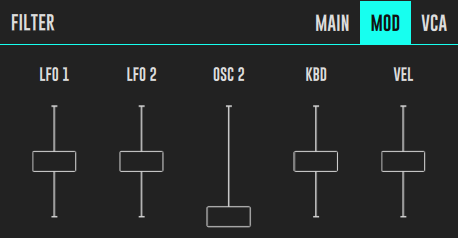
The MOD TAB represents the Filter Modulation Section of DRC. You use the sliders to inject modulation in the Filter. All modulation goes to the Filter Frequency with the exception of VEL (Velocity - the velocity or force with which you press a keyboard key). VEL injects this force sensing control voltage in the EG 2 AMOUNT which in turn affects the Frequency, but in this way with an envelope instead of a constant voltage.
Controls
-
LFO 1 - This slider controls the amount of LFO1 control voltage that affects the Filter Cutoff. You change all the characteristics of the LFO1 waveform in the MODIFIERS PANEL > LFO 1 TAB.
-
LFO 2 - The same as LFO1 but this time the slider controls the amount of LFO2 control voltage that affects the Filter Cutoff. You change all the characteristics of the LFO2 waveform in the MODIFIERS PANEL > LFO 2 TAB.
-
OSC 2 - This slider allows you to inject the output waveform of OS2 as a control voltage to the Filter Frequency. This type of modulation is a bit more uncommon and produces a very characteristic harsh texture to the sound. Try adjusting the OSC 2 COARSE and FINE parameters to get interesting interactions between the sound that enters the Filter and OSC 2 Modulation. A very sought-after synth that uses this technique is the ARP 2600 semi modular synth.
-
KBD - The KBD slider allows you to track the Filter Frequency to the notes you are playing in the keyboard. You can think of it as a control voltage that is dependent of the note that you are playing and is injected in as a Filter Cutoff Modulation. This allows for you to dial a sound that being somewhat filtered, is still more or less consistent as you go up or down in the keyboard. This slider is bipolar meaning that you have no effect in the center, as you go up you give a positive effect and going below half way you are dialing a negative effect.
-
VEL - The VEL slider allow you to control EG 2 AMT with a control voltage that is analogous of the velocity or force with which you press a key in a keyboard (a midi keyboard that has velocity sensing). This is a lot more expressive than to merely inject this control voltage in the Filter Cutoff. This slider is bipolar meaning that you have no effect in the center, as you go up you give a positive effect and going below half way you are dialing a negative effect.
Voltage Controlled Amplitude

Parameters
-
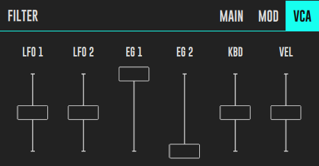
LFO 1 - This slider controls the amount of LFO1 control voltage that affects the amplification factor of the VCA. You can use LFO’s here to make tremolo kind of effects. You can change all the characteristics of the LFO1 waveform in the MODIFIERS PANEL > LFO 1 TAB.
-
LFO 2 - The same as LFO 1 but this time the slider controls the amount of LFO2 control voltage that affects the amplification factor of the VCA. You can change all the characteristics of the LFO2 waveform in the MODIFIERS PANEL > LFO 2 TAB.
-
EG 1 - EG 1 is the default modifier of the VCA. The EG 1 slider controls the amount of EG 1 that modulates the amplitude of the sound. You can use it to make fast abrupt tones or slow and sustained ones. You use it mostly maxed out as per default, but you can dose it in conjunction with EG 2 amount to make more intricate envelope curves. You can change all parameters regarding EG 1 in the MODIFIERS PANEL > EG 1 TAB.
-
EG 2 - This slider allow you to inject EG 2 (the EG that is hardwired to the Filter) as an amplitude modulation of your signal. You can change all parameters regarding EG 2 in the MODIFIERS PANEL > EG 2 TAB.
-
KBD - The KBD slider allows you to track the VCA Amplitude to the notes you are playing in the keyboard. You can think of it as a control voltage that is dependent of the note that you are playing and is allowed to control the VCA Amplitude. This make sit possible to increase or decrease amplitude as you go up or down the keyboard which can be very useful in some circumstances, mostly when you are also using KBD modulation in other places. This slider is bipolar meaning that you have no effect in the center, as you go up you give a positive effect and going below half way you are dialing a negative effect.
-
VEL - The VEL slider allow you to control the VCA Amplitude with a control voltage that is analogous of the velocity or force with which you press a key in a keyboard (a midi keyboard that has velocity sensing). This is analogous of what happens in most instruments which produce a louder sound as you play them harder. This slider is bipolar meaning that you have no effect in the center, as you go up you give a positive effect and going below half way you are dialing a negative effect.
