FX Devices
AUDIO UNIT
BAM allows loading external Audio Unit v3 plugin effects. For information on exposing AUv3 plugin parameters for mapping, automation and modulation see the Device Rack section.
AUv3 presets are browsable in a drop-down menu in the rack panel.
BIT REDUCTION
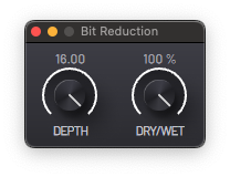
Degrade the audio bit depth, introducing audible quantization error artifacts.
- DEPTH - Audio bit depth.
- DRY/WET - Mix between the unprocessed and processed signals.
BURNER
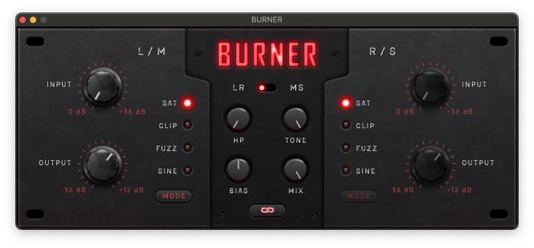
This is a distortion device that can alter the sound from subtle amplification gain saturation to clipping and fuzz effects. The link switch toggles the channel link, allowing separate processing of the left and right (or mid and side, if MS mode is enabled) channels.
- INPUT - Input gain.
- OUTPUT - Post distortion output volume control.
- MODE - Distortion mode.
- SAT - Saturation.
- CLAP - Hard clipping.
- FUZZ - Fuzz distortion.
- SINE - Sinusoidal wave folding.
- LR/MS - Stereo/Mid-side mode switch.
- LR - Process the left and right channels individually.
- MS - Allows processing only the mono or stereo parts of the sound.
- HP - Cutoff frequency of the high-pass filter affecting the input signal.
- TONE - Cutoff frequency of the low-pass filter affection the output signal.
- BIAS - Input signal DC bias; affects the generated harmonic content and general timbre.
- MIX - Mix between the unprocessed and processed signals.
- LINK - Toggle channel link.
CHORUS
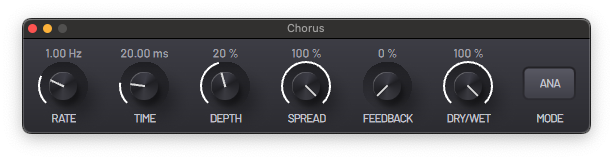
Stereo chorus effect (it converts mono signals to stereo) with two different algorithms. The CHORUS simulates the subtle pitch and timing differences that occur when multiple musicians or vocalists play the same note, but vary slightly in pitch and timing.
- RATE - Frequency of the modulations.
- TIME - Delay of the modulated signal.
- DEPTH - Modulation amount.
- SPREAD - Stereo image widening effect.
- FEEDBACK - Amount of signal to be fed back into the circuit.
- MODE - Switch between two different CHORUS algorithms.
- ANA - Analog.
- DIM - Dimension.
- DRY/WET - Mix between the unprocessed and processed signals.
COMPRESSOR
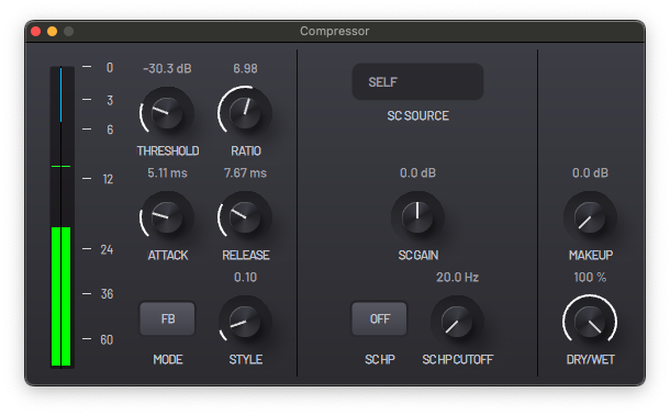
A flexible and versatile compressor with side-chain capabilities, suitable for controlling audio transients and managing perceived loudness.
- THRESHOLD - Level at which the compressor starts acting.
- RATIO - Gain reduction ratio applied to the input signal above the threshold.
- ATTACK - Time it takes for the gain reduction to be fully applied after the signal surpasses the threshold.
- RELEASE - Time it takes for the gain reduction to fully dissipate after the signal goes below the threshold.
- MODE - Select between feedforward and feedback compression algorithms.
- FF - The gain reduction is based on the clean input signal.
- FB - The compressed output is fed back into the sidechain, meaning the compressor reacts to the signal after it has already been compressed. This makes the gain reduction soften over time.
- STYLE - Control the character of the gain reduction envelopes.
- A lower value results in very fast envelopes and can result in ripples and distortion similar to a FET compressor. A higher value behaves like a cleaner VCA compressor.
Side Chain
- SC SOURCE - Source for the compressor's analysis signal.
- SC GAIN - Input volume of the compressor's analysis signal.
- SC HP - Enable the analysis signal high-pass filter.
- SC HP CUTOFF - Cutoff frequency of the high-pass filter.
Master
- MAKEUP - Volume control of the output signal, used to rebalance the perceived loudness after the compression.
- DRY/WET - Mix between the unprocessed and processed signals.
DELAY
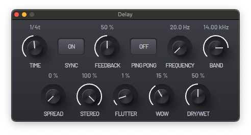
A virtual stereo tape delay. This delay has tape emulation controls, a custom filter and stereo parameters.
- TIME - Delay time between the repetitions of the signal.
- SYNC - Synchronize the delay time to project tempo.
- FEEDBACK - Amount of the output signal fed back into the circuit.
- PING PONG - Enables ping-pong mode, where the delay bounces back and forth between the left and right channels.
- FREQUENCY - Starting point of the frequency band filtering the signal.
- BAND - Bandwidth of the frequency band.
- SPREAD - Add a delay to the right channel.
- STEREO WIDTH - Amount of pan separation between the left and right signals of the output.
- FLUTTER - Amount of fast frequency modulation generated by the flutter of a tape machine.
- WOW - Amount of slow frequency modulation generated by the playback speed variations of a tap machine.
- DRY/WET - Mix between the unprocessed and processed signals.
EQUALIZER
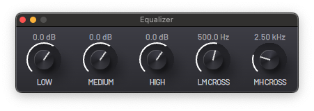
A three-band equalizer with controllable bandwidth parameters, ideal as a frequency band cut or frequency band isolator.
- LOW - Low frequency band gain.
- MEDIUM - Medium frequency band gain.
- HIGH - High frequency band gain.
- LM CROSS - Frequency of the crossover between the low and medium frequency filters.
- MH CROSS - Frequency of the crossover between the medium and high frequency filters.
FILTER
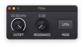
A multi-mode filter with 6 different modes.
- CUTOFF - Filter cutoff frequency.
- RESONANCE - Resonance or Q factor of the filter; creates a resonant peak at the cutoff frequency.
- MODE - Filter mode.
- L4P - 4 pole Low-pass Filter (24dB/oct attenuation) - A low-pass filter allows low frequency content to pass through, cutting high frequency content at a rate defined by the number of poles. This filter is a digital implementation of the Moog Transistor Ladder Filter.
- L2P - 2 pole Low-pass Filter (12dB/oct - thus less frequency cutting effect than the L4P) - This filter is a digital implementation of an analog multi-mode filter topology in the low-pass mode.
- B2P - 2 pole Band-pass Filter (12dB/oct) - A band-pass filter allows only a restricted frequency band to pass through, attenuating frequencies above and below. In this filter the Q factor has a particular importance as it somewhat defines the bandwidth that can pass through the filter. This filter represents the band-pass output of the analog multi-mode filter implementation.
- H2P - 2 pole High-pass Filter (12dB/oct) - A high -pass filter allows high frequency content to pass through, attenuating low frequency content. This filter represents the high-pass output of the analog multi-mode filter implementation.
- NOTCH - Notch Filter - A notch filter is a filter that cuts a very
restricted band of frequencies. The Q factor designates how narrow the
band is. Can be used to achieve a phaser-like effect, especially
when modulating the cutoff. This filter is also a product of the multi-mode filter topology used in the other filters (except L4P). - PEAK - Peak Filter - A peak filter amplifies a frequency band with the resonance determining the amplification amount and creating a resonant peak at high values.
PARAMETRIC EQ
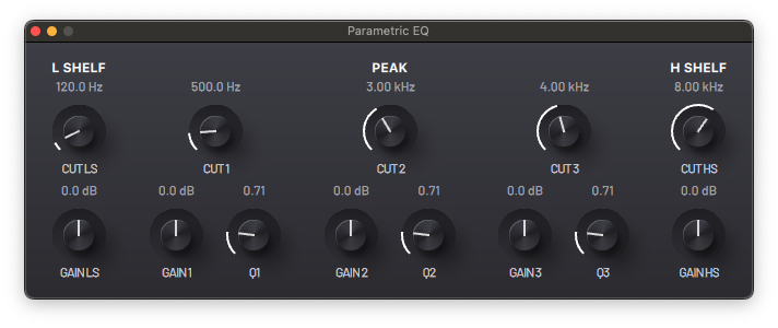
This is a parametric equalizer with low and high shelf controls and three peak filters with controllable cutoff frequency and Q factor.
L Shelf
A low shelf filter amplifies/attenuates all of the frequency content below the cutoff frequency.
- CUT LS - Cutoff frequency.
- GAIN LS - Gain control.
Peak
Three peak filters are available. These filters amplify/attenuate a frequency band according to the gain and Q factor controls.
- CUT - Cutoff frequency of the filter; determines the centre of the frequency band.
- GAIN - Amplification/attenuation control of the frequency band.
- Q - Q factor; controls the width of the frequency band.
H Shelf
A high shelf filter amplifies/attenuates all of the frequency content above the cutoff frequency.
- CUT HS - Cutoff frequency.
- GAIN HS - Gain control.
PHASER
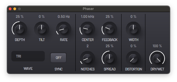
A phaser introduces a comb filter like effect by creating a series of notches in the frequency spectrum around a center frequency. This center frequency is modulated by controllable LFOs.
- DEPTH - Modulation depth of the notch frequencies.
- TILT - Change modulation rates of left and right channel LFOs; negative values speed up the left LFO and slow down the right one, and vice versa.
- RATE - LFO rates.
- WAVE - LFO waveforms.
- SYNC - Synchronize LFO rates to project tempo.
- CENTER - Center frequency of the phaser; notches are grouped around this point.
- FEEDBACK - Amount of signal to be fed back into the circuit.
- NOTCHES - Number of notches.
- SPREAD - Control the distance between the notches.
- WIDTH - Create a difference in the center frequencies of the left and right channels.
- DISTORTION - Distort the output signal.
- DRY/WET - Mix between the unprocessed and processed signals.
REVERB
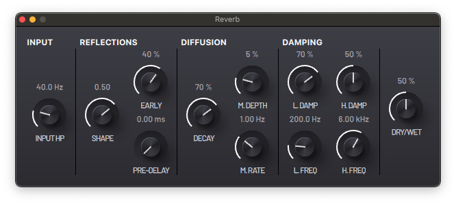
This is a reverb effect that can recreate different acoustic spaces from small rooms to long halls.
Input
- INPUT FILTER - Cutoff frequency of the high-pass filter affecting the input signal.
Reflections
- EARLY - Amount of first reflections.
- SHAPE - Control the size and type of simulated space.
- PRE-DELAY - Control the distance between the sound source and the first reflections.
Diffusion
- DECAY - Decay rate of the reflections
- M.DEPTH - Amount of frequency modulation of the reflections
- M.RATE - Rate of frequency modulation of the reflections
Damping
- H.DAMP - Damping of the high frequency band of the reflections.
- H.FREQ - Cutoff frequency of the high frequency damper.
- L.DAMP - Damping of the low frequency band of the reflections.
- L.FREQ - Cutoff frequency of the low frequency damper.
Output
- GAIN - Wet signal output gain.
- DRY/WET - Mix between the unprocessed and processed signals.
STEREO ENHANCER
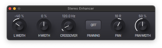
This device can change the apparent width and stereo position of audio signals. Using the panning controls, a stereo image can be created from mono signals.
The crossover filter allows you to separate the signal into two frequency bands and control their stereo images independently.
- L WIDTH - Stereo width of the low frequency band.
- H WIDTH - Stereo width of the high frequency band.
- CROSSOVER - Frequency of the crossover.
- PANNING - Enable panning controls.
- PAN - Position of the signal in the stereo image.
- PAN WIDTH - Control the stereo width of the signal.