Engine Devices
AUDIO UNIT
BAM allows loading external Audio Unit v3 plugin instruments. For information on exposing AUv3 plugin parameters for mapping, automation and modulation see the Device Rack section.
AUv3 presets are browsable in a drop-down menu in the rack panel.
SAMPLER
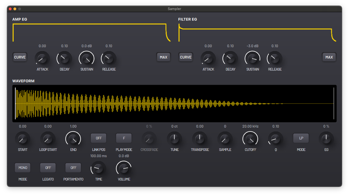
BAM’s SAMPLER is an easy to use sampler with a streamlined set of features and an intuitive minimal interface. It includes a range of playback modes, legato and portamento functions, tuning controls and a multi-mode filter.
The Sampler can load samples from the Pool, or work as a single sample engine. The SOURCE button toggles between the two modes. Dragging a sample onto the Sampler or onto the engine slot will load it as a single sample engine.
In POOL mode, the ‘SAMPLE’ parameter control lets you switch between samples from the project’s sample pool.
The interface has 4 different tabs: Sample, Envelopes, Filter and Master.
Sample
- START - Starting point of playback.
- END - End point of playback.
- LOOP START - Starting point of the loop when in a looping mode.
- LINK POS - Link START, END and LOOP START positions.
- PLAY MODE - Select playback mode.
- F - Play forward without looping.
- FL - Play forward and loop.
- FLPP - Play forward and loop back and forth in a ping pong manner.
- B - Play backward.
- BL - Play backward and loop.
- BLPP - Play backward and loop back and forth in a ping pong manner.
- CROSSFADE - Length of the crossfade between start and end loop points.
- SAMPLE - Select sample from the sample pool. Enabled when SOURCE is in POOL mode.
- SOURCE - Sample source.
- POOL - Play the samples loaded into the Pool. The SAMPLE control determines which Pool item is played.
- LOAD - Play a loaded sample. Samples can be loaded by dragging a sample from the Browser onto the Sampler or an engine slot.
Envelopes
The amplitude envelope controls the volume of the sound over time, visually represented by the yellow line. The envelope can be interacted with directly by dragging different parts of the line on both x and y axis.
All filter envelope parameters are the same as in the amplitude envelope but applied to the cutoff frequency of the filter rather than the amplitude of the sound.
- CURVE - Provide access to individual controls to define non-linear
curve shapes for the attack, decay and release stages of the envelope.
- A.Curve - Define the curve for the ATTACK phase.
- D.Curve - Define the curve for the DECAY phase.
- R.Curve - Define the curve for the RELEASE phase.
- INV - Inverts the envelope so that the volume amplitude starts and ends at maximum.
- ATTACK - The time it takes for the sound to reach its peak volume after the start of a note.
- DECAY - The time it takes for the volume of the sound to transition to its SUSTAIN value while the note is held.
- SUSTAIN - The volume of the sound after the ATTACK and DECAY stages of the envelope while the note is held.
- RELEASE - Time it takes for the volume of the sound to transition from its SUSTAIN value to its final value after the note is released.
- MAX - Opens controls to adjust the scale/range of the ATTACK, DECAY
and RELEASE knobs by defining the maximum duration value for each knob.
- A.MAX - Maximum ATTACK time available.
- D.MAX - Maximum DECAY time available.
- R.MAX - Maximum RELEASE time available.
Filter
The SAMPLER features a 2 pole multi-mode resonant filter.
- CUTOFF - Filter cutoff frequency.
- Q - Resonance or Q factor of the filter; creates a resonant peak at the cutoff frequency.
- MODE - Filter mode.
- LP - Low-pass.
- BP - Band-pass.
- HP - High-pass.
- NOTCH - Band reject.
- EG - Amount of the envelope generator affecting the filter's cutoff.
MASTER
- TUNE - Fine tuning in cents.
- TRANSPOSE - Base pitch in semitones.
- PORTAMENTO - Toggle a slide between notes when they are overlapped rather than an instant pitch change.
- TIME - (If PORTAMENTO is enabled) this designates the time it takes for a note to pitch slide to the next played note.
- MODE - Select between Mono (only plays one note at a time) and Poly (plays up to 8 voices at a time).
- LEGATO - Toggle Legato style note transitions on or off. With LEGATO on and in MONO mode, the notes change without retriggering the envelope generators.
- VOLUME - Controls the output volume.
OSCILLATOR
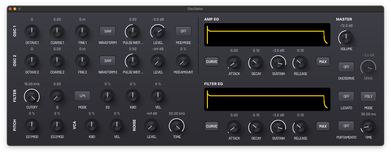
A subtractive analogue modeling synthesizer with two independent oscillators and a noise generator as its main audio sources. It is also capable of Ring and Frequency Modulation. It features a multi-mode filter and a saturation circuit.
Osc 1
- OCTAVE 1 - Select octave.
- COARSE 1 - Pitch control in semitones.
- FINE 1 - Fine tune in cents.
- WAVEFORM - Base waveform shape.
- PULSE WIDTH - Pulse width of the square waveform, from an even square to an infinitely thin pulse.
- LEVEL - Output volume.
- MOD MODE - Select modulation mode.
- Ring - Perform ring modulation with OSC 2.
- FM - Perform frequency modulation with OSC 2.
- MOD AMOUNT - Modulation amount between OSC 1 and OSC 2.
Osc 2
All parameters are the same as in OSC 1 with the exception of the modulation controls.
Filter
- CUTOFF - Filter cutoff frequency.
- Q - Resonance or Q factor of the filter; creates a resonant peak at the cutoff frequency.
- MODE - Filter mode.
- L4P - 4 pole Low-pass Filter (24dB/oct attenuation) - A low-pass filter allows low frequency content to pass through, cutting high frequency content at a rate defined by the number of poles. This filter is a digital implementation of the Moog Transistor Ladder Filter.
- L2P - 2 pole Low-pass Filter (12dB/oct - thus less frequency cutting effect than the L4P) - This filter is a digital implementation of an analog multi-mode filter topology in the low-pass mode.
- B2P - 2 pole Band-pass Filter (12dB/oct) - A band-pass filter allows only a restricted frequency band to pass through, attenuating frequencies above and below. In this filter the Q factor has a particular importance as it somewhat defines the bandwidth that can pass through the filter. This filter represents the band-pass output of the analog multi-mode filter implementation.
- H2P - 2 pole High-pass Filter (12dB/oct) - A high -pass filter allows high frequency content to pass through, attenuating low frequency content. This filter represents the high-pass output of the analog multi-mode filter implementation.
- NOTCH - Notch Filter - A notch filter is a filter that cuts a very
restricted band of frequencies. The Q factor designates how narrow the
band is. Can be used to achieve a phaser-like effect, especially
when modulating the cutoff. This filter is also a product of the multi-mode filter topology used in the other filters (except L4P).
- EG - Amount of the envelope generator affecting the filter's cutoff.
- KBD - Modulate the cutoff frequency with the pitch of the played notes.
- VEL - Modulate the cutoff frequency with the velocity of the played notes.
Pitch
- EG1 MOD - Amount of pitch modulation from the Amplitude Envelope.
- EG2 MOD - Amount of pitch modulation from the Filter Envelope.
VCA
- KBD - Modulate the volume of the oscillators with the pitch of the played notes.
- VEL - Modulate the volume of the oscillators with the velocity of the played notes.
Noise
- LEVEL - Volume of the noise generator.
- TONE - Cutoff frequency of low-pass filter.
Amplitude and Filter Envelopes
The amplitude envelope controls the volume of the sound over time, visually represented by the yellow line. The envelope can be interacted with directly by dragging different parts of the line on both x and y axis.
All filter envelope parameters are the same as in the amplitude envelope but applied to the cutoff frequency of the filter rather than the amplitude of the sound.
The envelopes can be adjusted with the following parameters:
- CURVE - Provide access to individual controls to define non-linear
curve shapes for the attack, decay and release stages of the envelope.
- A.Curve - Define the curve for the ATTACK phase.
- D.Curve - Define the curve for the DECAY phase.
- R.Curve - Define the curve for the RELEASE phase.
- INV - Inverts the envelope so that the volume amplitude starts and ends at maximum.
- ATTACK - The time it takes for the sound to reach its peak volume after the start of a note.
- DECAY - The time it takes for the volume of the sound to transition to its SUSTAIN value while the note is held.
- SUSTAIN - The volume of the sound after the ATTACK and DECAY stages of the envelope while the note is held.
- RELEASE - Time it takes for the volume of the sound to transition from its SUSTAIN value to its final value after the note is released.
- MAX - Opens controls to adjust the scale/range of the ATTACK, DECAY
and RELEASE knobs by defining the maximum duration value for each knob.
- A.MAX - Maximum ATTACK time available.
- D.MAX - Maximum DECAY time available.
- R.MAX - Maximum RELEASE time available.
Master
- VOLUME - Control the output volume.
- OVERDRIVE - Enable saturation on the main signal.
- DRIVE - (If OVERDRIVE is enabled) control the drive of the main signal.
- LEGATO - Toggle Legato style note transitions on or off. With LEGATO on and in Mono mode, the notes change without retriggering the envelope generators.
- MODE - Select between Mono (only plays one note at a time), Poly (plays up to 8 voices at a time) and Unison (plays all 8 voices simultaneously with slight detune).
- PORTAMENTO - Toggle a slide between notes when they are overlapped rather than an instant pitch change.
- TIME - (If PORTAMENTO is enabled) this designates the time it takes for a note to pitch slide to the next played note.
DRUM SYNTH
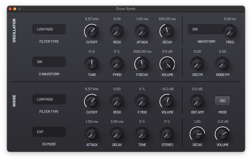
A synthesizer specifically engineered for creating drum sounds. It has an oscillator with a filter, a noise generator with different noise sources, a filter and stereo controls. It also has a frequency modulation section and a saturation stage.
Oscillator
-
FILTER TYPE - Select between the different available filter modes (Low-pass, Band-pass, High-pass, Notch and Peak).
-
CUTOFF - Filter cutoff frequency.
-
RESO - Resonance or Q factor of the filter; creates a resonant peak at the cutoff frequency.
-
ATTACK - The time it takes for the sound to reach its peak volume after the start of a note.
-
DECAY - The time it takes for the sound to fall from peak volume to zero.
-
WAVEFORM - Shape of the waveform.
-
TUNE - Fine tuning of the pitch in cents.
-
P MOD - Pitch modulation amount.
-
P DECAY - Decay time of the pitch modulation envelope.
- Note that this envelope also modulates the Noise filter cutoff.
-
VOLUME - Volume of the oscillator output.
Noise
- FILTER TYPE - Select between the different available filter modes (Low-pass, Band-pass, High-pass, Notch and Peak).
- CUTOFF - Filter cutoff frequency.
- RESO - Resonance or Q factor of the filter; creates a resonant peak at the cutoff frequency.
- F.MOD - Filter cutoff frequency modulation amount.
- Note that this cutoff frequency is modulated by the Oscillator's pitch envelope.
- EG MODE - Select the behavior of the envelope generator.
- EXP - Exponential curve.
- SHORT - Short decay times.
- CLAP - Multiple impulse envelope to create a rattling sound. Use the Attack parameter to control the time between impulses.
- ATTACK - The time it takes for the sound to reach its peak volume after the start of a note.
- DECAY - The time it takes for the sound to fall from peak volume to zero.
- TONE - Cutoff frequency of low-pass filter.
- STEREO - Stereo width.
- VOLUME - Volume of the noise output.
Modulation
Perform frequency modulation on the Oscillator pitch and/or the Noise filter cutoff.
- WAVEFORM - Modulation waveform.
- FREQ - Modulation frequency.
- OSC FM - Amount of oscillator frequency modulation.
- NOISE FM - Amount of noise filter cutoff modulation.
Distortion
- DIST AMT - Distortion amount.
- MODE - Select distortion signal chain (Oscillator, Noise or both).
Master
- DECAY - Global decay control.
- VOLUME - Global master output volume.
HOFMANN
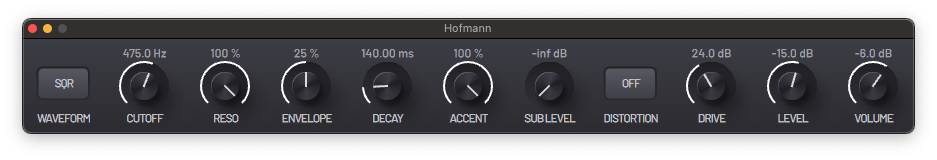
A monophonic synthesizer with an oscillator, a sub-oscillator and a filter, physically modeled after the most famous classic acid synth in history.
- WAVEFORM - Toggle between square and sawtooth.
- CUTOFF - Cutoff frequency of the low-pass filter.
- RESO - Resonance of the filter; creates a resonant peak at the cutoff frequency.
- ENVELOPE - Amount of filter cutoff envelope modulation.
- DECAY - The time it takes for the amplitude and filter envelopes to fall from peak amplitude to zero.
- ACCENT - Amount of accent modulation of the note.
- An accent is triggered when the velocity of a note is over 100. Accent notes default to a short decay time and have higher amplitude and filter envelope modulation.
- SUB LEVEL - Volume of the sub oscillator, which is a square wave regardless of the WAVEFORM.
- DISTORTION - Enable distortion of the main signal.
- DRIVE - (If DISTORTION is enabled) control the drive of the main signal.
- LEVEL - (If DISTORTION is enabled) level of the main signal after distortion.
- VOLUME - Control the output volume.
NOISE
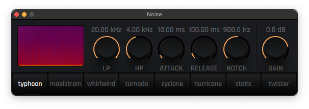
A creative noise generator with different noise sources, three different filters and a simple envelope generator.
- SOURCE - Select between eight different types of noise.
- LP CUTOFF - Cutoff frequency of the low-pass filter.
- HP CUTOFF - Cutoff frequency of the high-pass filter.
- ATTACK - The time it takes for the sound to reach its peak volume after the start of a note.
- RELEASE - The time it takes for the sound to fall from peak volume to zero.
- NOTCH - Cutoff frequency of the notch filter.
- GAIN - Control the output volume.
‘08’ ENGINES COLLECTION
Virtual analogue models of the sounds of the iconic drum machine. All engines have an ACCENT parameter which affects the sound for notes with a velocity value of over 100.
08 KICK
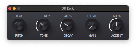
- PITCH - Generator fine tune in cents.
- TONE - Low-pass filter cutoff; useful for attenuating the "clicky" transient of the sound.
- DECAY - The time it takes for the amplitude envelope to fall from peak volume to zero.
- GAIN - Control the output volume.
- ACCENT - Amount of accent modulation.
08 SNARE
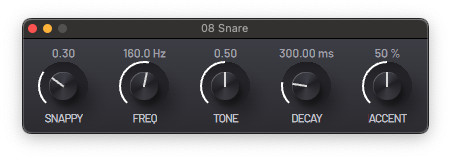
- SNAPPY - Volume of the noise generator.
- FREQ - Oscillators pitch.
- TONE - Volume relation between the synth's two oscillators.
- DECAY - The time it takes for the noise's amplitude envelope to fall from peak volume to zero.
- ACCENT - Amount of accent modulation.
08 CLAP
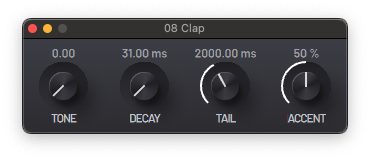
- TONE - Cutoff frequency of resonant filter.
- DECAY - Length of the retriggering noise clap oscillators.
- TAIL - Length of the continuous noise generator sound.
- ACCENT - Amount of accent modulation.
08 TOM CONGA
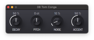
- DECAY - The time it takes for the amplitude envelope to fall from peak volume to zero.
- PITCH - Generator fine tune in cents.
- NOISE - Volume of the noise generator.
- ACCENT - Amount of accent modulation.
08 HI-HAT
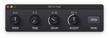
- PITCH - Generator fine tune in cents.
- TONE - Brightness amount.
- DECAY - The time it takes for the amplitude envelope to fall from peak volume to zero.
- ACCENT - Amount of accent modulation.
- MODE - Select between the OPEN and CLOSED hi-hat modes.
08 COWBELL
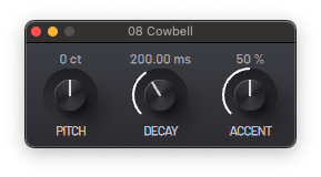
- PITCH - Generator fine tune in cents.
- DECAY - The time it takes for the amplitude envelope to fall from peak volume to zero.
- ACCENT - Amount of accent modulation.
AUDIO INPUT
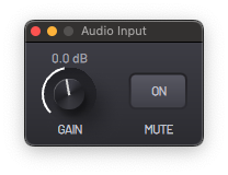
An audio input for processing external sources inside BAM (such as a microphone or an external synthesizer).
- GAIN - Input signal volume control
- MUTE - Mute audio input
- SOURCE - Input channel configuration.
MIDI OUT
The MIDI Out engine enables routing MIDI output to external devices.
Bank, Sub-Bank, Program, Pitchbend and Aftertouch controls are provided by default. You may add additional CC parameters.
By directly changing, mapping and/or automating the existing parameters, you can output MIDI messages to the selected DEVICE and CHANNEL.
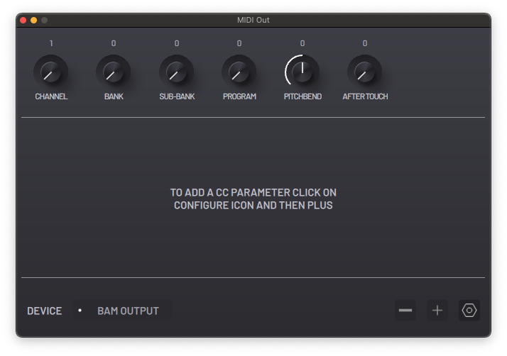
- DEVICE - The MIDI device to send MIDI to (press to open scrollable drop down menu).
- CHANNEL - Select MIDI channel to output to.
- BANK - Send MIDI Bank message.
- SUB-BANK - Send MIDI Sub-Bank message.
- PROGRAM - Send MIDI Program Change message.
- PITCHBEND - Send MIDI Pitchbend message.
- AFTERTOUCH - Send MIDI Aftertouch message.