Material Editor: Making your own shaders
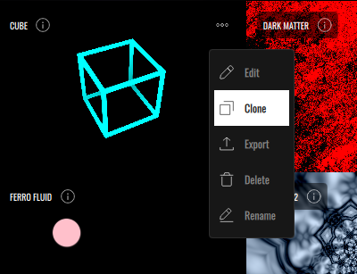
VS’s built-in Material Editor allows editing and creating your own GLSL fragment shaders. The simplest way to create a new shader is to clone and edit an existing one from the Material Editor. When you clone a shader material, it will automatically open the editor window. Your edited shaders are saved under Shaders → User Materials in the Material Browser.
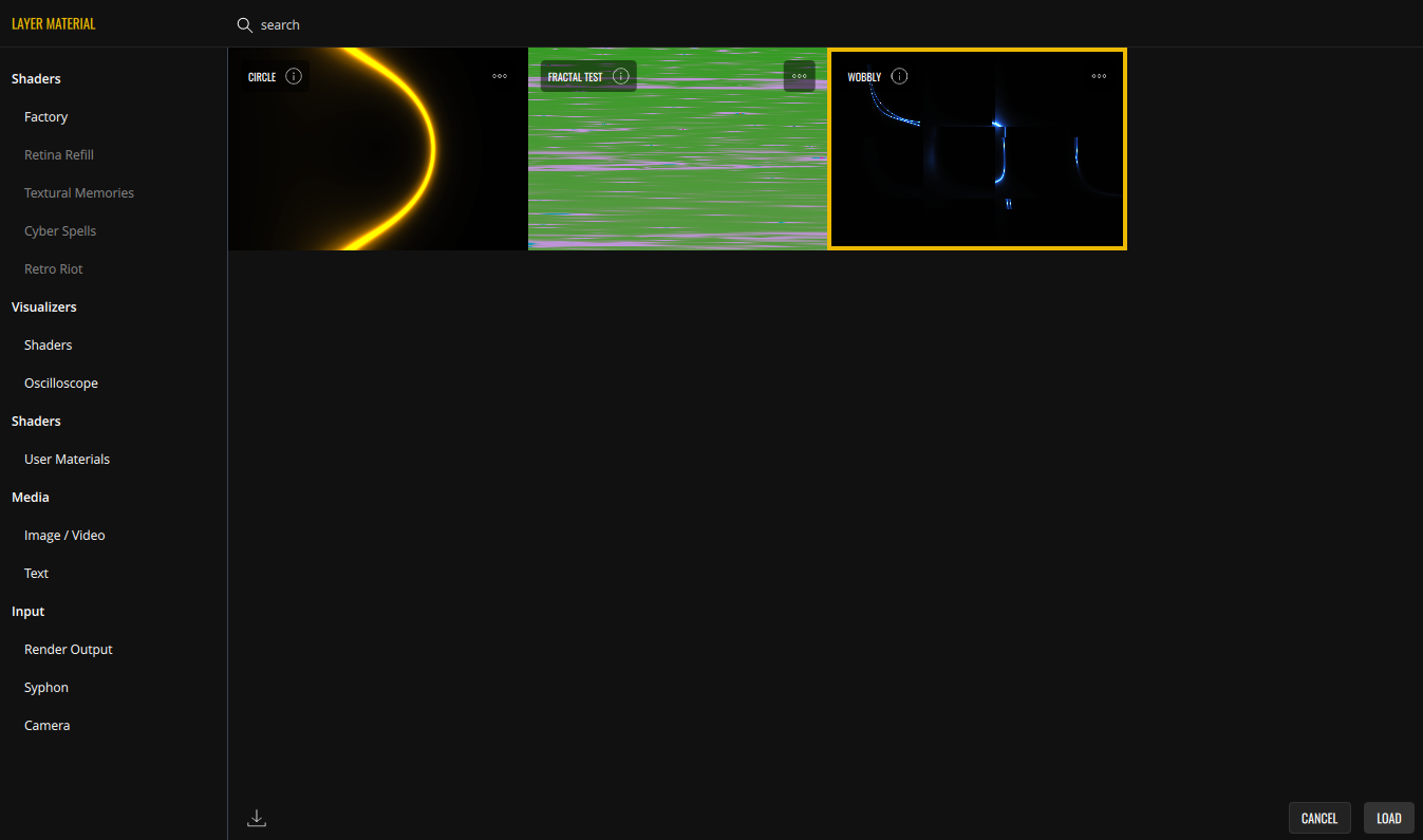
You can also import shader materials using the Import button  located in the bottom left corner.
VS's Material Editor consists of a text editor, a live preview window and a set of knobs representing the standard and custom material parameters.
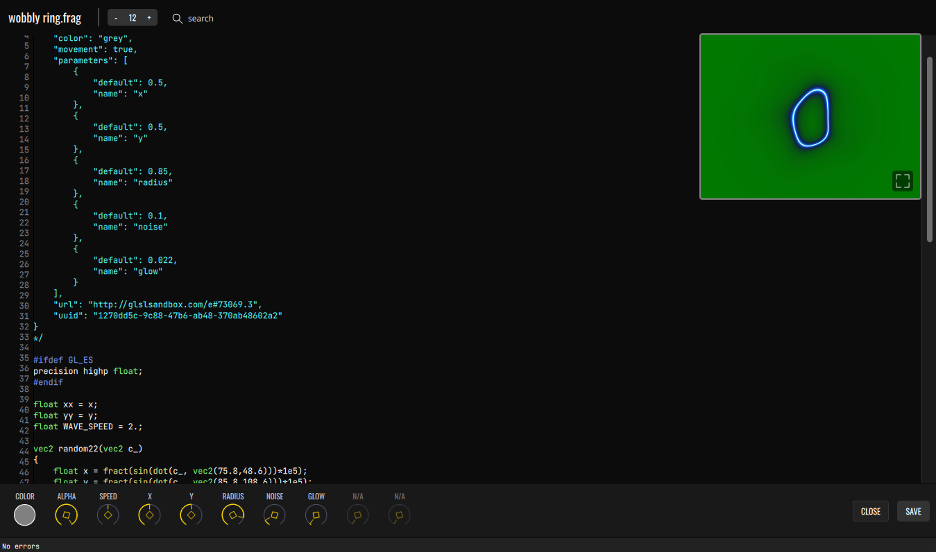
Every time a change is made in the code, the shader material will be updated. If the code is right and there are no errors, the preview window will update with your changes. The preview window can be moved by dragging, and can be made full screen by clicking the full screen icon in its corner. To close the full screen preview, double click on the preview area.
Structure of a shader
VS shaders follow a structure similar to ISF (Interactive Shader Format), but the two formats are not identical or compatible with each other. This means that if you import an ISF shader as a new shader material into VS, it will not work immediately.
Each shader’s source code starts with a manifest (commented JSON block) which declares the shader’s properties/parameters. A shader must have a manifest in order to load correctly.
Here is an example:
/*
{
    "author": "",
    "color": "white",
    "movement": true,
    "parameters": [
        {
            "default": 0.5,
            "name": "x"
        },
        {
            "default": 0.5,
            "name": "y"
        },
        {
            "default": 0.75,
            "name": "spread",
            "min" : 0.1,
            "max" : 5,
        }
    ],
    "url": "",
    "uuid": "babfc75f-178c-44e3-9ef5-89208122f156"
}
*/
Every manifest must have the following properties:
- uuid - Unique identifier. When a shader is cloned, a new uuid is automatically generated. You can create new uuids at https://www.uuidgenerator.net/
- color - Default color. It can be an SVG (Scalable Vector Graphics) named color or a hex string starting with # (eg: #ff0000).
- movement (either 'true' or 'false') - If set to true, will enable the speed layer parameter.
The following properties are optional:
- parameters - An array of JSON objects with name, default, min (optional), max (optional) properties. Min and max, if not declared, are 0 and 1 by default.
- url - URL to shader’s author/source.
- author
The example shader above declares three parameters: 'x', 'y' and 'spread', which become available as variables for use in the code.
Note: A parameter’s default value must be normalized (between 0 and 1). Despite this, min and max are real values, not normalized. For example, for a parameter that ranges from 0 to 4, a default of 0.5 will place the value at 2.
Environment variables
There are specific pre-declared environment variables to be aware of. Keep these in mind when editing your shaders:
- time (highp float) - Linked with the Layer’s ‘Speed’ parameter.
- alpha (highp float) - Linked with the Layer’s ‘Alpha’ parameter, controlled through the Mixer slider.
- color (highp vec4) - Linked with the Layer’s color.
- resolution (highp vec2) - Holds the viewport resolution.
- texCoord (highp vec2) - Holds the texture coordinates, normalized between 0 and 1.
- fragColor (highp vec4) - Equivalent to gl_FragColor. Copy your final pixel color to this variable and it will be displayed.
Cloning shaders from the Factory bank and reading the code is the best way of learning how VS shader materials work.
Adapting a GLSL shader for VS usage
GLSL fragment shaders are a highly complex topic that requires a good understanding of computer graphics, as well as deep knowledge of mathematics — something we are by no means masters of.
Still, if you are brave enough to take on this challenge, we recommend reading The Book of Shaders as a starting point. It’s an incredible online resource written by Patricio Gonzales Vivo.
We do feel that it is important to mention some of the most basic caveats of converting a typical GLSL fragment shader code to be compatible with VS. Let's take the circle shader code from The Book of Shaders as an example.
float circle(in vec2 _st, in float _radius)
{
    vec2 dist = _st-vec2(0.5);
	return 1.-smoothstep(_radius-(_radius*0.01), _radius+(_radius*0.01), dot(dist,dist)*4.0);
}

void main()
{
	vec2 st = gl_FragCoord.xy/u_resolution.xy;
	vec3 color = vec3(circle(st,0.9));

	gl_FragColor = vec4( color, 1.0 );
}
If you paste the following code into VS material editor after the manifest, it will show nothing but green and display an error, as u_resolution and gl_FragColor are not declared variables. Replace u_resolution with resolution and gl_FragColor with fragColor, our environment variables. Refer back to Structure of a shader for a list of usable environment variables.
No more errors will be displayed and the preview will turn black. However, nothing seems to be displayed yet. If you drag the window to the top-left side of the editor window, you will see a deformed white circle — it’s being drawn with no regard to the viewport position or size.
In order to paint inside the preview window, we must use the 'texCoord' variable that holds the normalized texture coordinates. In order to do this, replace the line:
vec2 st = gl_FragCoord.xy/resolution.xy;
with
vec2 st = texCoord;
Now the circle is positioned within the bounds of the preview window. However, it’s vertically squashed. Since texCoord holds normalized positions, it doesn't take into account that the display window might not be a square. This results in the height and width of the rendered circle being stretched proportionally to the viewport’s height and width.
We need to calculate the ratio ourselves. This is done in most of the factory materials. If you replace:
vec2 st = texCoord;
with
float div = resolution.y/resolution.x;
vec2 aspect = vec2(1.,div);
vec2 st = texCoord*aspect;
You will see that the circle now has the right proportions, but is going outside of the window bounds. With some further tweaks for better positioning, we end up with the following code:
float circle(in vec2 _st, in float _radius)
{
    vec2 dist = _st;
	return 1.-smoothstep(_radius-(_radius*0.01),
                         _radius+(_radius*0.01),
                         dot(dist,dist)*4.0);
}

void main()
{
	float div = resolution.y/resolution.x;
    vec2 aspect = vec2(1.,div);
	vec2 st = texCoord*aspect-vec2(0.5, 0.5*div);

	vec3 color = vec3(circle(st, 0.3));

	fragColor = vec4( color, 1.0 );
}
So now that we have a centered circle drawn in the preview, let's take advantage of the built-in variables to control alpha, color, and brightness. Then, let’s add parameters to the manifest to control the circle's x, y position and radius.
/*
{
    "author": "",
    "color": "violet",
    "movement": true,
    "parameters": [
        {
            "default": 0.5,
            "name": "x"
        },
        {
            "default": 0.5,
            "name": "y"
        },
        {
            "default": 0.1,
            "name": "radius",
			"min": 0.1,
			"max": 2
        }
    ],
    "url": "",
    "uuid": "1823757c-871c-4057-baee-8c69a8ff1ff8"
}
*/

#ifdef GL_ES
precision highp float;
#endif

float circle(in vec2 _st, in float _radius)
{
    vec2 dist = _st;
	return 1.-smoothstep(_radius-(_radius*0.01),
                         _radius+(_radius*0.01),
                         dot(dist,dist)*4.0);
}

void main()
{
	float div = resolution.y/resolution.x;
    vec2 aspect = vec2(1.,div);
	vec2 st = texCoord*aspect-vec2(x, y*div);

	vec3 c = vec3(circle(st, abs(sin(time))*0.4+radius));

	vec3 finalColor = vec3(c);
	float coloredPixels = dot(clamp(finalColor, 0., 1.), vec3(1.0));
	fragColor = vec4(finalColor * color.rgb, alpha * coloredPixels);
}
Take special notice of the last 3 lines. We’re obtaining coloredPixels — a float variable indicating how far from black a pixel is — and using it for our final opacity. This turns the black background transparent. It’s important to have transparency in your VS shaders for the visual “voices” to overlay properly and for other, underlying layers to remain visible. For more information on this, check Migrating shaders from VS 1.
Previous: VS as a plug-in in your DAW
Next: Migrating shaders from VS 1