Layer Modulations
This panel is divided into three sections: LFOs, envelopes and audio modulation. These are audio related terms that we chose to adopt so people using this software with their audio compositions can feel at home in the visual world also.
However, if you’re new to these terms we will happily explain them right now.
Modulation Sources
LFO
This is an acronym for Low Frequency Oscillator. LFOs are signals with very low frequencies, whose output can be used to modulate audio signals (like frequency, volume, etc). We took this concept and applied it to the materials/layers parameters. You can, for instance, take the x position of a given material, and modulate it with an LFO, so its position is changed over time.
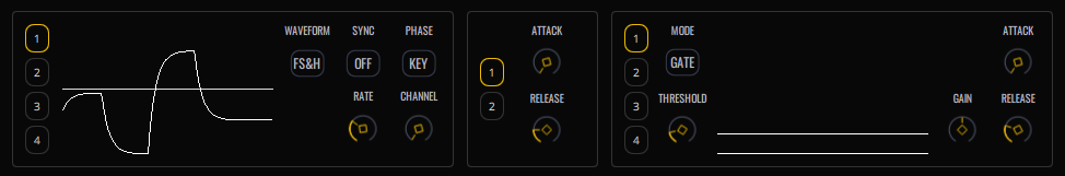
On the left of the panel is the LFOs section. There are 4 independent LFOs, accessed using the numbered buttons, and each LFO consists of the following parameters:
-
Waveform - Click to cycle through these available types:
- SINE - Sinusoidal
- SQR - Square
- SAW - Sawtooth
- TRI - Triangle
- S&H - Sample and hold (this will give you jumps between random values for modulation)
- FS&H - Filtered sample and hold (the same as sample and hold but there will be a ramp between values, causing smooth glides between random values rather than jumps)
-
Rate - Define the speed of the LFO. This will set the frequency of the oscillation that will determine how fast the values are changed
-
Sync - When active, the speed of the LFO can be set to various increments of the tempo of the VS project, so you can have your modulations in sync with the tempo of your session
-
Phase - You can choose between FREE and KEY. In key mode, the LFO will always start from the 0 value anytime a MIDI ‘note on’ event is received. This is useful to have expected results every time you receive a trigger note, i.e. the modulation effect will always start from the same position. In free mode the LFO will run freely.
-
Key - (only enabled when phase is set to 'key') This allows you to specify a particular MIDI channel to listen for 'note on' events, or to listen for 'note on' events on all MIDI channels by setting it to 'Any'.
A visual representation of the waveform is shown to the left of the controls.
Note: playing with the LFOs will only produce visible changes when they have been assigned to targets in the Modulation Matrix (see below for details).
EG
EG is an acronym for envelope generator. In audio terms, the envelope generator shapes the sound amplitude over time.
Envelope generators usually have four stages: Attack, decay, sustain and release, also known as ‘ADSR’. VS streamlines the envelope generator process by requiring just the attack and release parameters.
In audio terms, the attack stage is how long it takes for a sound to reach its sustain value from the moment it is triggered, and the release is the amount of time the sound will take to reach silence, once the note has been released. In simplified terms, you can think of attack as fade in, and release as fade out. Then you have two parameters to control in the EG:
-
Attack - controls the amount of time the brightness will take from zero to its layer defined value once a trigger on event (note on) is received
-
Release - controls the amount of time the brightness will take from its sustain value to zero once a trigger off event (note off) is received
We provide you two independent EGs to choose from.
Note: by default EG1 is set to modulate layer BRIGHTNESS parameter in the modulation matrix. This allows a layer to be “played” with notes on/off when TRIGGER mode is set to MIDI. When a note on event is received, BRIGHTNESS will ramp from 0 to its level, in ATTACK time. You can change this at any time in the matrix modulation panel.
Note: bear in mind that the EG is just like an LFO, a way for you to have a signal that can act as a modulator. But while the LFO is always running, the EG needs a trigger to activate its attack stage, and another trigger to activate its release stage. Then you can use it to modulate the available parameters in the matrix panel.
Audio Modulators
Finally, on the right of the modulators panel there is the audio modulator panel. Here it’s possible to use the input audio as a modulation source, just like the LFOs and EGs.
There are four independent audio modulators, with two modes of operation:
-
GATE - in this mode audio input will serve as a modulator only if its amplitude is above a specific level, defined by the THRESHOLD parameter. There is a visual analyser, so it is possible to see the amplitude range of the input and adjust the threshold accordingly. When the audio signal passes the defined threshold, it will work as an envelope follower. In order words, the amount of modulation will be linked to the ‘strength’ of the signal. The greater the amplitude, the greater the value of the modulation.
-
SPCTRM (Spectrum) - This mode is very similar to the gate mode, but with the advantage of the audio being “divided” into frequency bands. Instead of reading the amplitude of the signal as a whole, you can choose a specific band of frequencies to serve as a modulation source. You can, for instance, try to capture a kick, or a snare, or maybe a specific high or low sound from your input, and use it as a modulator. The threshold is equally applied in this mode.
Remember that each audio modulator is independent, so you can have different audio modulators capturing different bands with different thresholds, or combining gate ones with spectrum ones. Again, remember that like the LFOs or EG2, playing with these will produce no effect unless they have been assigned to something in the Modulation Matrix, discussed below.
Audio modulator parameters:
- Numbered boxes - select the desired audio modulator Mode - Select the mode of the current audio modulator (Gate or Spectrum)
- Threshold - Define the limit where the input will start to be used as modulation
- Gain - This serves as a multiplier of the resulting modulation values. It can be useful to amplify quieter signals or to reduce strong ones
- Attack - As explained above, the attack is related to the amount of time a given signal takes to reach the maximum value as soon as there is an on trigger. In this case, we consider the signal passing the threshold as the trigger, and its current value as the target. So what attack will do is to make a kind of ramp between values. The greater the amount of attack, the slower it will change the output of the modulator. In other words, longer attacks will cause slower onset of modulations
- Release - This is triggered when the signal passes below the threshold, and defines the time the output modulation will take to reach the zero value. In other words, longer release values will cause modulations to fade more slowly
Modulation Matrix
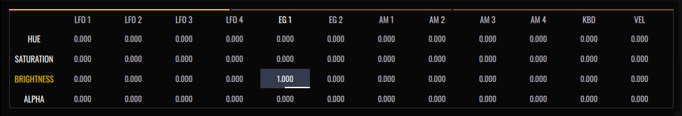
The modulation matrix panel lets you assign modulation sources to specific layer parameters, arranged in a two dimensional grid of cells, with modulation sources on the x axis (top) and parameters on the y axis (left). Clicking a cell value and then dragging either up/down or left/right will decrease or increase the amount of modulation effect that the source will have on the parameter. This value can range from -1 to +1, with the default setting zero representing no modulation effect. To aid visual clarity, each cell shows a white horizontal line under the value, if the value is greater than or less than zero. The origin point of the line is centered, so positive values draw to the right and negative to the left.
The matrix is split into three tabs, with a thin yellow bar highlighting the currently displayed tab, click each yellow tab line to access the different pages of each layer’s parameters. You can also click and hold layer parameter rotary knobs to quickly navigate to its corresponding matrix cell (for this to work, the layer parameter must exist in the matrix).
In addition to the LFO, EG and AM (audio modulator) modulation sources, a further two sources are available for MIDI note data trigger based modulation:
- KBD (Keyboard) - the amount of modulation determined by the pitch of the note on events. The MIDI pitch 60 corresponds to the zero point of the modulation. Pitches higher will act as increasing positive modulation and pitches lower will act as decreasing negative modulation
- VEL (Velocity) - the amount of modulation determined by the velocity of the MIDI note on events
Tip: to reset all of a layer’s matrix values to zero, click and hold the layer button, located on the render area, select ‘reset’ from the pop-up menu, then select the ‘modulation matrix’ radio button and click reset.